Disassembling Tesla Wall Connector Firmware
Recap
In a previous post, we examined the Tesla wall connector firmware file used to update the wall connector. Tesla’s binary file is a container file with a file magic of SBFH and holds metadata about another firmware container inside the file. The second inner firmware container is for the 88MW30x WiFi chips. This chip-specific firmware contains metadata in a header for where different code segments are located in the file and where those code segments are loaded into the hardware’s memory.
In this post, we’ll continue building an understanding of the firmware in preparation for disassembly and higher-order reverse engineering. We’ll see how the code is aligned in memory and begin to set a foundation for recognizing the structure of the disassembled code.
Loading firmware in Ghidra
There are many different tools for disassembling bare-metal firmware. For example, we could use IDA Pro, Binary Ninja, or Ghidra. I will use Ghidra here to show how we can load up the firmware and correctly represent the memory regions for the 88MW30x chipset. Since software references many things like code, input/output, read-only memory, or random access memory, having a correct representation of the memory regions in Ghidra makes understanding the core of the code easier.
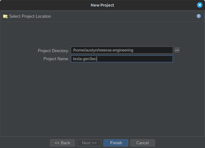
To start, we’ll open Ghidra and create a new project.
 |
|---|
| Create a new Ghidra project |
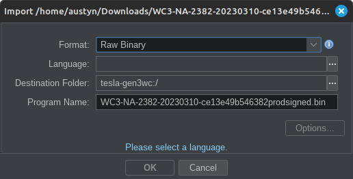
After creating the project, import the firmware we downloaded. Easiest way to import the firmware binary file to the project is by dragging and dropping the file into the Active Project tree view area.
 |
|---|
| Import the firmware binary into Ghidra |
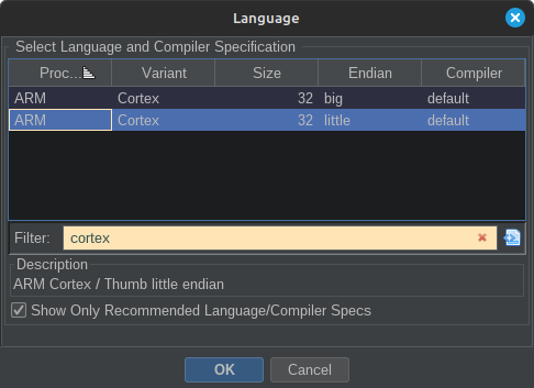
Before pressing OK, we must tell Ghidra which language the binary file is encoded in. After reading through the 88MW30x datasheet, we know this chip is powered by an ARM Cortex-M4 CPU and uses little-endian memory space. Press the ellipsis (...) next to the Language: text box and search for cortex. The WiFi chip uses the ARM Cortex-M4 processor, with instructions in little-endian format. Select this language, and we’ll be one step closer to seeing some code!
 |
|---|
| Set the firmware’s language for little-endian ARM Cortex-M4 |
Now that we’ve told Ghidra the processor architecture and the byte order of the instructions, we can finally open the firmware up in the disassembler. Think the code will automatically disassemble, the functions will correctly call other functions, and the code will correctly reference hard-coded strings? You’re correct if you’ve noticed a trend and thought nope! The disassembler can decode the instructions, but because many of the instructions reference memory addresses within an expected section of memory, we have to tell Ghidra exactly where the code is in memory. Luckily for us, we know that we’re dealing with the 88MW30x chipset, and it has a datasheet that tells us everything we need to understand.
Clues for Memory Mapping
Vector Table
When dealing with bare metal ARM firmware binaries, we can sometimes rely on the ARM hardware requirements to help guide us toward the memory addresses the code expects to be. Occasionally, the very first word (i.e., 4 bytes) in the file is the address of the stack. Then, there will be a list of addresses for import functions the processor will use for interrupts. This table is called the vector table. Each ARM processor is designed slightly differently, so the order or number of functions may differ. In general, think about it like this: If programming ARM chip X, the very first 4 bytes of the firmware may be the address to use as the stack. The next 4-bytes may be the address of the RESET function. The next 4-bytes may be the address for another function. Another processor may have its RESET function represented by the 5th word from the start of the firmware file. Still, if the compile toolchain knows what processor you’re compiling for and correctly writes the vector table, then the firmware can reference all the correct code at all the proper addresses. Luckily, this table can provide clues on where the code expects to be loaded in memory.
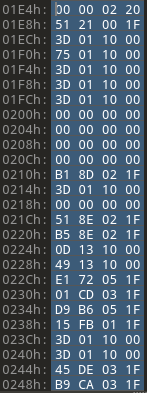
Look at the image below. Assuming the first word is the stack address, the stack is at 0x20020000. Remember, the firmware is loaded in little-endian byte order on 32-bit architecture. When we read the numbers in the file, we first read the least significant byte.
 |
|---|
| First words of firmware |
Because we’re looking for significant memory ranges, we don’t particularly care what the least significant bytes of the words actually contain. We’re trying to understand the most significant bytes to determine where the code is loaded. Nowadays, people may want to use machine learning to find patterns, but luckily, we can tell by looking. Quite a few addresses start 0x1F0????? and 0x0010????. We’ll jot these addresses down and keep investigating to find other clues that either help confirm what we think so far or counter our assumptions.
Hard-coded Addresses
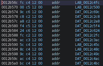
Sometimes, compilers will encode instructions that have relative offsets to where the current instruction point is. For example, a control flow instruction like a branch (pnemonic b or hex 0xe1) may tell the processor how many bytes from the current instruction to jump to before executing instructions again. In this instance, all we would see in the hex disassembly is a relative offset. Other instructions like the load (ldr) tell the processor to look x-relative-bytes away from where the current instruction pointer is and load the 4 bytes into memory. Sometimes, those 4-bytes will be hard-coded addresses or at least already have the most significant bytes match with where the firmware expects to be loaded in memory.
We are going off the assumption that the code could be loaded at 0x1F0????? or maybe 0x0010????. Luckily for us, the firmware file is big enough that we can scroll down to the bytes around 0x0010???? and see if there are a lot of data references. When scrolling that portion of the code, there is a lot of code referencing memory in this 0x001????? region. These addresses themselves are not terribly helpful, but they do help amplify our belief that the firmware should be loaded somewhere closer to 0x1F?????? or 0x001????? instead of at 0x00000000 where we have it now.
 |
|---|
| Some Hard-coded addresses |
Datasheets
Datasheets are generally the go-to source for understanding the memory layout of the firmware for a given microcontroller. I wanted to avoid leading off with this method because the datasheets are only sometimes available for a specific microcontroller, which you may be reverse engineering.
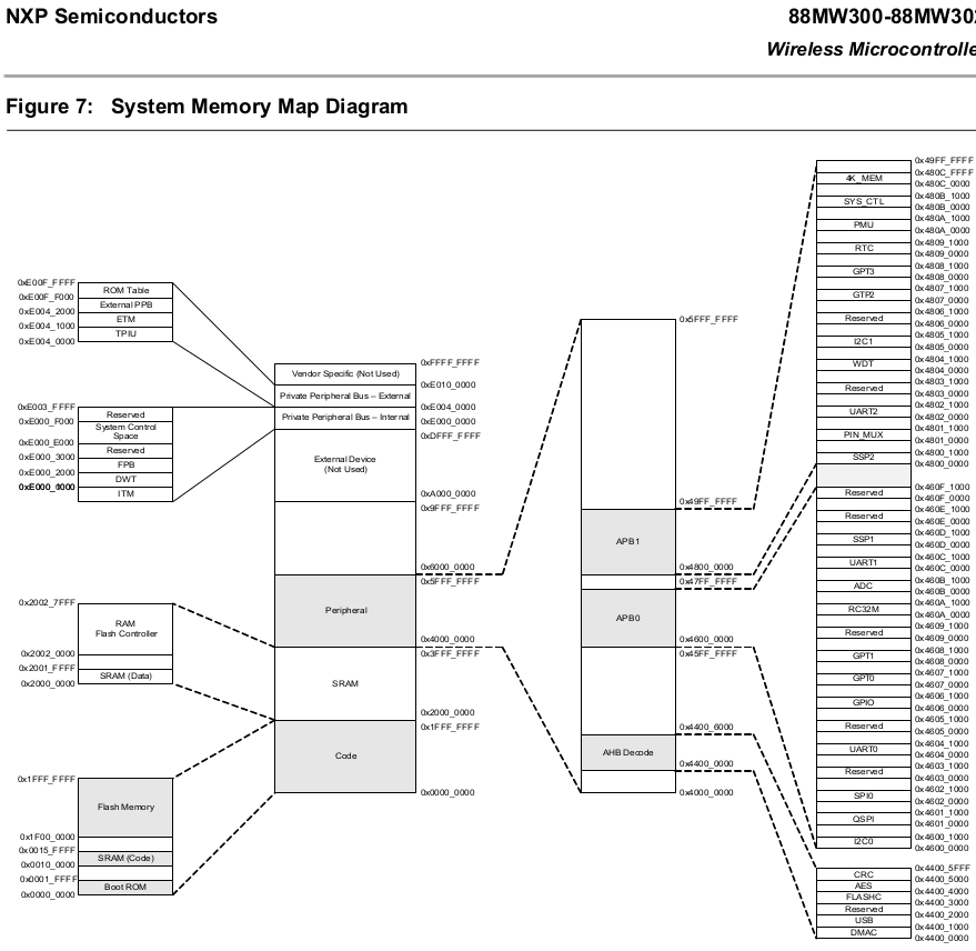
In this instance, we know we’re dealing with the 88MW30x microcontroller, and we can find the datasheet provided by the manufacturer. The datasheet will typically give a memory map diagram that shows what the microcontroller’s memory addresses correspond to. The image below is a snip of the datasheet.
 |
|---|
| Memory map diagram for the 88MW30x Wireless Microcontroller |
From the start, we can see the SRAM (Code) from 0x00100000 to 0x0015FFFF. This is good and somewhat jives with the address we thought contained the code. Next, the Flash Memory goes from 0x1F000000 to 0x1FFFFFFF. Again, this range includes values for some addresses we thought could be used for the firmware.
The datasheet confirms where the code could be loaded in memory. However, these memory ranges are just the allowed area for Code, Flash, etc. The code is not guaranteed to be loaded precisely at 0x00100000. For all we know, Tesla could play games with us and configure the firmware to start at 0x00142069 or something. We’ll look at another source to confirm where the code should load in memory.
Previous Reverse Engineering
In a previous post, we looked at the structure of the firmware container files and discovered some fields that represented virtual memory addresses for code segments. If the firmware file is following the structure we think it is for the 88MW30x microcontroller, we should be able to go back and look at those addresses for the fidelity we need. Suppose the firmware metadata falls anywhere within the general 0x1F?????? or 0x001????? ranges we’ve identified so far. In that case, loading the firmware at those specific addresses will likely result in properly disassembling the firmware.
What we can see from the Marvell metadata is that the firmware segments should be mapped to the following memory location:
- Segment 1:
0x00100000 - Segment 2:
0x1F002150 - Segment 3:
0x20000040
Now, we have all the information to ensure the correct parts of the firmware file are loaded and mapped to the proper memory addresses. We know where the bytes for the code segments are because the firmware segment headers tell us the offset in the file and the size of the segment. We see the start and end sizes of the microcontroller memory regions because of the datasheet. And we know where the first bytes of the firmware code segments are loaded into the memory. The next thing to do is configure all these memory mappings in Ghidra and see if the code analysis is any more meaningful than the first naive analysis we did.
Configuring Memory Regions in Ghidra
Before showing what it looks like to configure the memory regions in Ghidra correctly, I want to indicate how the code looks when we naively load a binary file. This intends to show indicators that our process or approach is going in the right direction or not. Too often, we only see the right way to solve technical reverse-engineering problems but miss an opportunity to notice what subsumes the bulk of our time: messing up.
Often, you may hear references to firmware images for a device like a router. A router’s firmware image differs significantly from what we’re dealing with. A router’s firmware will have a significant known data structure that we can use to unpack a known file system format and extract executable files containing code. For example, the code could be in a familiar and well-known format such as ELF. Loading an ELF file in Ghidra is trivial because all details about memory layout and code and data segments are specified in the loaded file itself, and Ghidra knows how to parse the ELF headers and load the code/data. We must have the luxury of Ghidra knowing how to parse our wall connector’s firmware. We could write our own loader, but we’ll understand this post’s requirements by manually loading the firmware.
Naive Disassembly
In this context, Naive disassembly lets Ghidra load the entire firmware file into a default memory address. We should intuitively know this needs to be corrected. The firmware file has some extra data before the actual code sections that comprise the firmware container file. We also saw in the previous section that this particular firmware file has three different code sections, and each section should be loaded into specific memory addresses. Though we know the correct memory addresses, let’s look at some indicators our firmware is loaded into the wrong memory.
Poor Code Coverage on Analysis
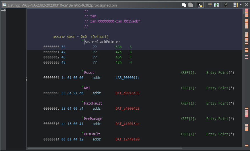
When we tell Ghidra to load the entire file into memory and not specify a memory address for where the code is loaded, by default, the whole file is treated like code and is loaded at address 0x00000000. We can see below that Ghidra is trying to treat the SBFH header of the firmware container as either data or code, which we know isn’t correct. We can also see the little orange outline blocks on the right of the image below; these are places in the file where the Ghidra analysis detected some ARM instructions and disassembled them. The disassembly above looks promising, but we should expect much more of the file to be disassembled in a raw firmware blob. Let’s examine for other indicators in the disassembly and string references that indicate we need to load the file entirely correctly.
 |
|---|
| Beginning of the Disassembly |
Undefined Data Around Functions
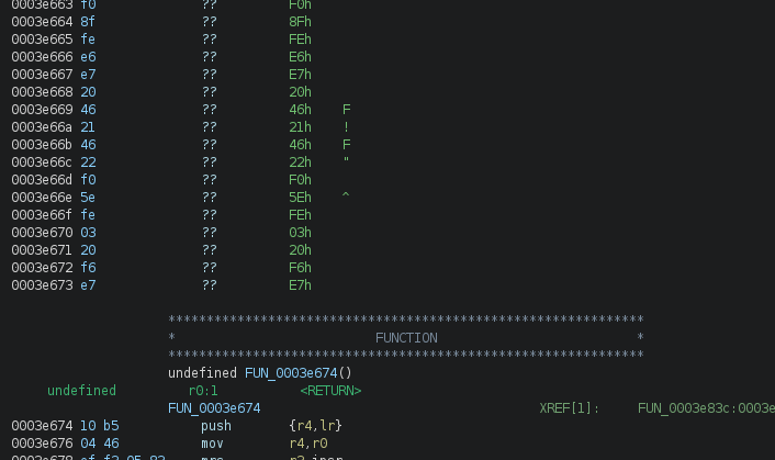
Another indicator that is often easy to spot and can help indicate the firmware isn’t loaded at the correct memory address is undefined bytes immediately before or after analyzed functions. Generally speaking, the data before or after a function will be another function or reserved memory referenced by the nearby function. For example, if a function references a string, the bytes of that string could immediately follow the function. Or if the function references a pointer to another memory address, that pointer could be hard-coded as some data immediately following the function. These are not the only reasons for having referenced bytes after a function; however, not having any initialized bytes can indicate that we still need to load the firmware into the correct memory mapping and adequately disassemble.
 |
|---|
| Unprocessed bytes around functions |
Unusual Disassembly Instructions
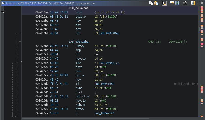
Showing patterns in the function’s disassembly is difficult in a document like this because we benefit from looking at many functions. Still, we can see some aspects to look for in the randomly selected function below. We notice that the function starts with the typical prologue of a push instruction, and there are some move and compare instructions, which are common and usual. But then we notice some it, mov.ge, itet, sub.gt, etc. These are all obviously valid instructions, but they are uncommon. As you scroll through more and more code, you may see an unusually high number of these less common instructions. While this alone isn’t necessarily an indicator, it is another data point that we may not have our code correctly loaded. Another indicator that may strike you as odd is how few functions reference any of the strings in the file. Next, we’ll see just how many strings are actually referenced.
 |
|---|
| Randomly selected Function Disassembly |
String References
Luckily for us, we do have readable strings in the file, and we cannot assume that all of them are referenced in the code, but there is a good chance that many of the strings are actually used. Some firmware images, like small radio frequency processors or digital signal processors, are likely not to have any strings. Because these processors perform highly specialized functions and don’t typically have human interactions, looking for string references is only sometimes helpful. Still, we can use it in our discovery process in this particular case.
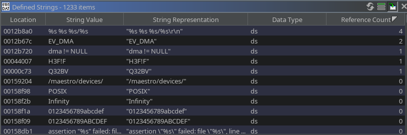
As we can see in the image below, there are about 1,000 readable strings. Note, this isn’t exact because Ghidra needs to know what are human-readable strings and what aren’t – it’s just looking for sequences of human-readable characters of a minimum length and guessing it’s a string. Of all thousand or so strings, only 5 of them are referenced anywhere in the code base. That seems unlikely, but why are so few referenced? Why wouldn’t the code load a hard-coded relative address to where the instruction is in the file? Firmware often relies on absolute addresses or pointers to other parts of the code or data, in this context, strings. Suppose the code is trying to reference an absolute address or pointer to a specific memory address, and we didn’t tell Ghidra to load the firmware, which includes the strings, to the expected address. In that case, the data will never be referenced.
Additionally, we saw earlier that significant amounts of code didn’t disassemble, and the code that disassembled into functions might not even be actual. In other words, Ghidra could have found a string of bytes correctly decoded to legitimate assembly instructions. However, suppose Ghidra would have started the analysis 1 byte or 2 bytes further into the file. In that case, you’d still have bytes of the file that could disassembly into legitimate but very different instructions.
 |
|---|
| Number of String References |
References to Middle of Strings
Another indicator I want to mention is when you see disassembled code reference in the middle of strings. While this doesn’t necessarily give us insights into where the code should be loaded, it indicates that we still need to load the code at the correct memory address.
 |
|---|
| Code references middle of string |
Arbitrary String Reference
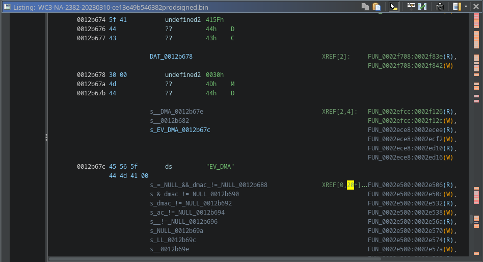
One thing to note is that the reference count above shows how many functions reference the string at the address where the string starts. If we click through multiple strings, we can see that there are actually hundreds of references to strings, but so many are at arbitrary locations within the string. A firmware image could have lots of strings compiled into it, like a string table or something, but none of the code referenced it. The compiler never optimized the unused data way. Still, when we see hundreds of strings with multiple references at arbitrary points within the string, we can safely assume we must correctly map the firmware to the proper memory regions.
 |
|---|
| Arbitrary String References |
Many other indicators seem a bit off and will give you the impression that the firmware needs to be entirely mapped to the correct location and disassembled correctly. To see what this firmware code actually looks like, we’ll now use what we’ve learned from the microprocessor’s datasheet and previous reverse engineering efforts of the firmware container file to help us get the firmware mapped to the correct memory.
Informed Disassembly
When we load the firmware into Ghidra’s CodeBrowser this time, we do not want to analyze it. It is not a big deal if you do analyze here, but we already know how the results will turn out. So skip the analysis, and we’ll start creating the memory blocks to match how the firmware expects to be loaded into memory.
 |
|---|
| Skip analysis of disassembly |
In the CodeBrowser’s main window, go to Window->Memory Map to open the Memory Map window. Here is where we will tell Ghidra the start and end addresses for different memory blocks. In addition to telling Ghidra the memory address, we will also tell Ghidra exactly where in the firmware file to pull the data to load into the memory blocks.
 |
|---|
| Default Ghidra Memory Map |
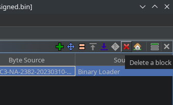
By default, Ghidra creates a memory block that starts at 0x0 and goes as many bytes as are contained in the firmware file we loaded. If we make our memory blocks, we will likely overlap the start address within the file’s length. To prevent the overlap, we delete all the blocks to have an empty map.
 |
|---|
| Delete Existing Memory Block |
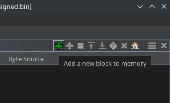
Now click the green plus icon to add a new memory block.
 |
|---|
| Add A Memory Block |
Finding the Right Memory Addresses
Instead of jumping into the disassembly and trying to brute force our way through memory addresses, we took our time before. We researched to understand the hardware requirements from the datasheet and file format of the firmware container file. That has provided us with all the necessary information to create these memory blocks.
We know the memory regions and names from the datasheet. We see the file offset where the firmware code starts for each memory segment. And we understand how much code there is to load into the memory segment. Since we’re doing static analysis, we don’t need to tell Ghidra the total size of the memory block like the datasheet shows because we only have a finite amount of code to load into the memory. The datasheet shows all the memory blocks, but that doesn’t mean programs have to use all the memory; only the amount of compiled code gets loaded into the memory, so that’s what we tell Ghidra for the size.
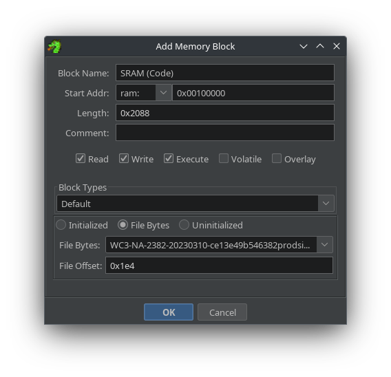
We can write out all the necessary details to add our three memory blocks with these variables.
- Segment 1 - SRAM (Code):
- mem start address:
0x00100000 - mem end address: 0x00100000 + 0x2088 =
0x00102088 - size: 0x2088
- file offset:
0x1e4
- mem start address:
- Segment 2 - Flash Memory
- start mem address:
0x1F002150 - end mem address: 0x1F002150 + 0x156e60 =
0x1f158fb0 - size: 0x156e60
- file offset:
0x226c
- start mem address:
- Segment 3 - SRAM (Data)
- start mem address:
0x20000040 - mem end address: 0x20000040 + 0x1cf4 =
0x20001d34 - size: 0x1cf4
- file offset:
0x1590cc
- start mem address:
One last thing to note is the permissions checkboxes. Since we have yet to learn what all the code does and how it interacts with other memory blocks, it’s typically easiest to check all three: Read, Write, and Execute. Otherwise, you will likely get incomplete disassembly. Try selecting only one or two or any combination of permissions to see how Ghidra’s disassembly performs.
 |
|---|
| Adding A Memory Block Details |
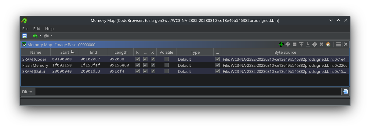
Below, we’ve added the three code segments extracted from the firmware file. This will adequately represent the firmware in memory as expected in the wall connector’s hardware and allow Ghidra to disassemble only the code without trying to interpret other meta-data parts of the firmware file container.
 |
|---|
| All three Memory Sections Mapped |
Of course, we don’t have to stop at these three particular memory blocks. I’m only showing them because they are part of the firmware file. The 88MW3xx datasheet shows a lot more memory regions. Adding those to this memory map could be hugely beneficial in understanding how code interacts with the hardware. For example, if we are searching the code for a function or functions that interact with the I2C data bus, then we might want to map the I2C0 and I2C1 peripheral memory addresses at 0x4600_0000-0x4600_0FFF and 0x4805_0000-0x4805_0FFF respectfully. Having these peripheral addresses mapped will help us identify any references to data or addresses within these regions and gain insights into the code we’re reverse engineering.
Seeing the Proper Disassembly
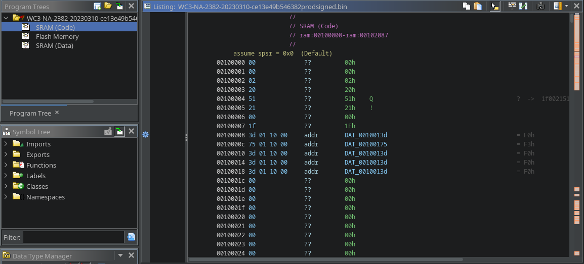
From the start, we can see below that Ghidra is no longer trying to load the SBFH portion of the file. We told Ghidra the file offset to load at a particular address. We could further improve this disassembly by adding labels to the vector table for the 88MW30x microcontroller.
 |
|---|
| Memory addresses are correct, and code coverage is much better |
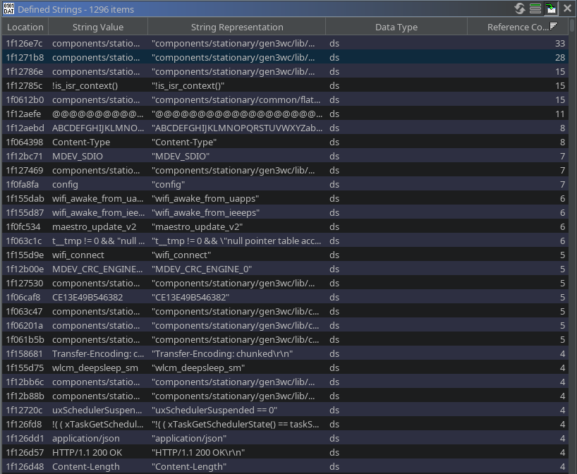
Likewise, many strings have multiple references throughout the code when looking at the defined string reference counts. If you glanced at the memory addresses of these strings (and surrounding ones), you’d see no references to the middle of these strings. The code is loaded correctly, and now we can continue our journey.
 |
|---|
| Significantly more referenced strings after memory-informed analysis |
Conclusion
In another attempt to lower the barrier to entry, we’ve looked at how to load firmware based on clues we’ve discovered from previous reverse engineering efforts. We also looked at clues in the firmware disassembly that may help us know if we correctly understand the code/firmware relations and if our disassembly is accurate. Lastly, we mapped the firmware correctly to memory and can look for the same clues as before to see if we are on the right path to successfully disassembling the firmware. Once successfully disassembled, we can begin the new journey of understanding what the code actually does.